HLSL Shaders
Introduction
This article will introduce you to the Direct3D 12 graphics pipeline and HLSL Shader Model 5. There are 5 main shader types; Vertex, Hull, Domain, Geometry and Pixel. This is the graphics pipeline of Direct3D 12 displaying in what order the shaders are applied.

Pipeline State
Before I can start explaining the different stages of the graphics pipeline I need to explain the pipeline state object (PSO). The IA, VS, HS, DS, GS, PS and OM are stored in a PSO. A PSO is a unified pipeline state object that is immutable after creation. The currently selected PSO can be changed quickly and dynamically, and the hardware and drivers can directly convert a PSO into native hardware instructions and state, readying the GPU for graphics processing. To apply a PSO, the hardware copies a minimal amount of pre-computed state directly to the hardware registers. The currently applied PSO defines and connects all of the shaders being used in the rendering pipeline. HLSL shaders can be precompiled into a shader object or compiled at runtime for debugging purposes.
Input Assambler
The input assambler reads the buffers created by the user to create primitives for other stages. The IA can can assemble vertices into several different Primitive Types.
Adjacency information available in the geometry shader. If a geometry shader were invoked with a triangle including adjacency, for instance, the input data would contain 3 vertices for each triangle and 3 vertices for adjacency data per triangle.
The secondary purpose of the Input Assambler is to attach system-generated values to help shaders to be faster. System-generated values are also called semantics. All three shader stages are constructed from a common shader core, and the shader core uses system-generated values (such as a primitive id, an instance id, or a vertex id) so that a shader stage can reduce processing to only those primitives, instances, or vertices that have not already been processed.
Vertex Shader
The vertex shader takes the data received from the IA (vertices and indices) and GPU buffers and modifies the data. We use this to create effects such as transformations, lighting and displacement mapping.
Hull and Domein Shader
The hull and domein shader are both part of the GPU’s Tesselessation process. These shaders are generally used to create high detail geometry from “Patches” (Low detail geometry). The hull shader takes an input patch and returns an output patch. The ouput of the hull shader runs trough the Tessellesation stage which produces domains.
The domein shader is takes those domains in order to compute the actual vertex position.
Geometry Shader
Unlike vertex shaders, which operate on a single vertex, the Geometry shader inputs are the vertices for a full primitive. For example the input primitive can be expanded into one or more other primtives. Earlier I said I won’t go into the Stream Output Stage since that is quite advanced but i’ll mention it here brievly: The geometry shader can stream-out vertex data into a buffer which can later be drawn. A example use can be things like grass, geometry tessellation and volumatric shadows.
Pixel Shader
The pixel shader is the final stage of the pipeline before we merge everything together. This shader is executed for every pixel fragment and is used to determine the color of said pixel. This can return a constant output or something more advanced like per-pixel lighting, reflections and shadows.
Output Merger
This stage may reject some of the pixel fragments from the pixel shader thanks to the depth. stencil and depth tests and render targets. The remaining pixels are drawn to the back buffer. Blending is also done in this stage.
Phong Shading
Phong shading is interpolation tecnique for surface rendering. Specificly it interpolates surface normals. Phong shading improves upon Gouraud Shading by providing better smoothing. But it does come at a performance cost. Phong shading can be stripped down to 3 parts: Ambient diffuse and specular. When we have calculated those 3 parts we can combine them. The result will look something like this:

Ambient
The ambient light is generally callculated with or without direction. So the ambient value will be quite easy to calculate::
Pixel Shader
float4 ambient_color = float4(1.f, 1.f, 1.f, 1.f);
float ambient_strength = 0.1f;

float4 ambient = ambient_color * ambient_strength;
Diffuse
Diffuse lighting gives the object more brightness the closer the fragments are aligned to the light rays from a light source. This image will explain it better than I can:
This images shows a light ray toutching a single fragment of a mesh. As you can see we need to calculate the angle of the light ray. To do this we use a normal vector. This can be calculated with the dot product. So there are 4 things we need for diffuse lighting, A normal vector, diffuse color, The fragmant’s position and a light direction. We can calculate the fragmant’s position by multiplying the model matrix with the vertex position. Now we have the fragment’s position we can also calculate the direction of the light by substracting the fragment’s position from the position of the light and normalizing the output since we want a directional vector.
Now we have all the nessessary calculations we can finally calculate the actual diffuse effect. We do this by taking the dot product of the normal and the light’s direction. Now we need to clamp the diffuse value to a minimum of 0 to prevent the diffuse effect to become negative when both the normal and light direction is greater than 90 degrees.
Pixel Shader
float3 light_dir = normalize(light_pos - input.fragment_pos);
input.normal = normalize(input.normal);
float diffuse_value = max(dot(norm, light_dir), 0.0);

float4 diffuse = diffuse_value * diffuse_color;
Specular
Just like diffuse lighting specular lighting is based on the light’s direction vector and the object’s normal. But now we will also need a view direction. We can think of specular lighting as a mirror. The light will be reflected in the material.
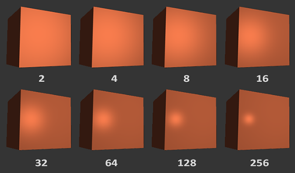
For the calculation we will use a specuilar strength variable, A shinyness variable which ranges from 2 to 256. The shinyness determines the scattering of the light. This image will show the result when changing the shinyness of the material:
Now lets get to the code and calculation. First we need a view direction and a reflection direction as mentioned above.
Now we calculate the specular vector by first calculating the dot product between the view direction and the reflect direction. Clamp it for the same reason as we clamped the diffuse value. And than multiply the outcome by the sinyness value.
And finally we multiply the specular value by the specular strength and light value to get the specular vector3.
float3 view_dir = normalize(frag_pos - view_pos);
float3 reflect_dir = reflect(light_dir, norm);

float specular_value = pow(max(dot(view_dir, reflect_dir), 0.0), shinynessss);
float3 specular = specular_strength * specular_value * light_color;
Rounding up
Now we just need to combine all the calculated vectors.
// Calculate Phong
float4 phong = ambient + diffuse + specular;
return phong;